This is the sole actuator utilized in the robot, featuring a high-torque-density electric motor paired with a backdrivable single-stage planetary gearbox, eliminating the need for additional sensors or compliance at the joints.
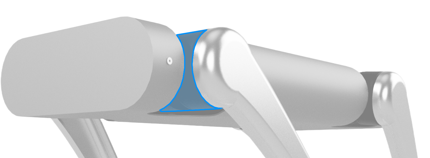
Emphasis was on a minimalist design that is affordable, lightweight, and robust.
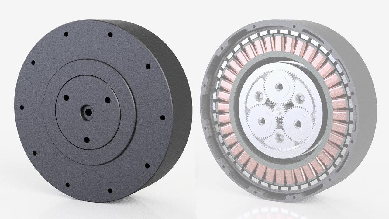
The BLDC motor comprises 47% of the weight, the gearbox 26%, and the casing and remaining parts make up the remaining 27%.
The actuator hardware accounts for 75% of the total cost, while the controller board makes up the remaining 25%.
Third-party suppliers provided the bldc motor, gears, and bearings, while I manufactured most of the casing and aluminum parts.
To determine the required characteristics for the actuator, which would enable the robot to execute actions such as walking, standing, and carrying payloads, a simulation of the robot performing these activities was conducted. From this simulation, a torque and velocity graph was extracted.
The resulting design features a bldc motor coupled to a single-stage planetary gearbox with a 9:1 reduction ratio. Utilizing a high-torque-density electric motor, a backdrivable single-stage planetary gearbox, and low-inertia legs, the robot is capable of controlling ground reaction forces without the need for force sensors, torque sensors, or series compliance at the joints.
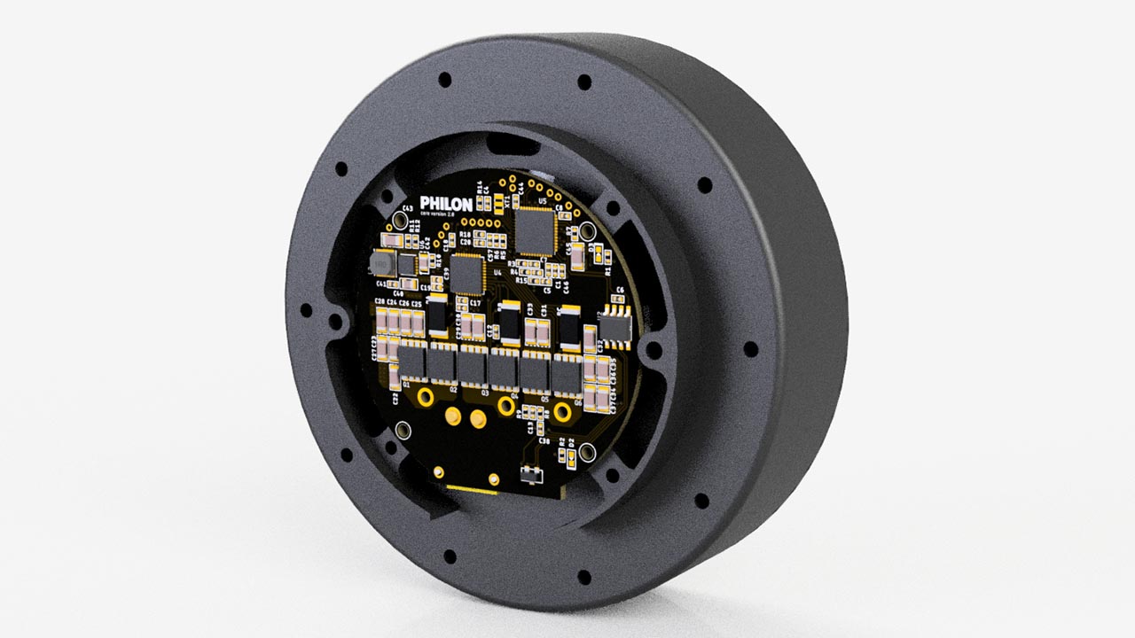
The board integrates a microcontroller and a motor driver IC. The microcontroller takes on the task of processing sensor data and implementing a Field-Oriented Control (FOC) strategy, generating PWM signals for each phase. These signals are subsequently fed into the motor driver IC.
To obtain the necessary feedback for the control loop, various sensors are in place: 3 current sensors (ia, ib, ic), an encoder and a thermistor which measures temperature to ensure that the motor operates within safe thermal limits.
A Finite State Machine (FSM), controls the different operational states and their transitions (Idle, Calibration, Commutation).
In the Commutation state, the system activates the Proportional-Derivative (PD) control module and employs a Field-Oriented Control (FOC) strategy.

The computer interfaces with the board through the CAN FD protocol. It sends commands specifying the desired torque, position, velocity, kp, and kd at a rate of 1khz.
In response, the computer receives updates on the current torque, position, velocity, and temperature of each motor.
Parameter |
Value |
Units |
|---|---|---|
| Input Voltage | 8 - 28 | V |
| Dimensions | 100 x 100 x 45 | MM |
| Pole Pairs | 21 | |
| Gear Ratio | 9:1 | |
| Backlash | 6 | Arc Min |
| Max Torque (Stopped testing at this value - potential for higher) |
30 | NM |
| Max Speed | 160 | RPM |
[1] MIT Mini Cheetah: A low cost modular actuator for dynamic robots
[2] Proprioceptive Actuator Design in the MIT Cheetah: Impact Mitigation and High-Bandwidth Physical Interaction for Dynamic Legged Robots